 English
 русский
 Español
 简体中文
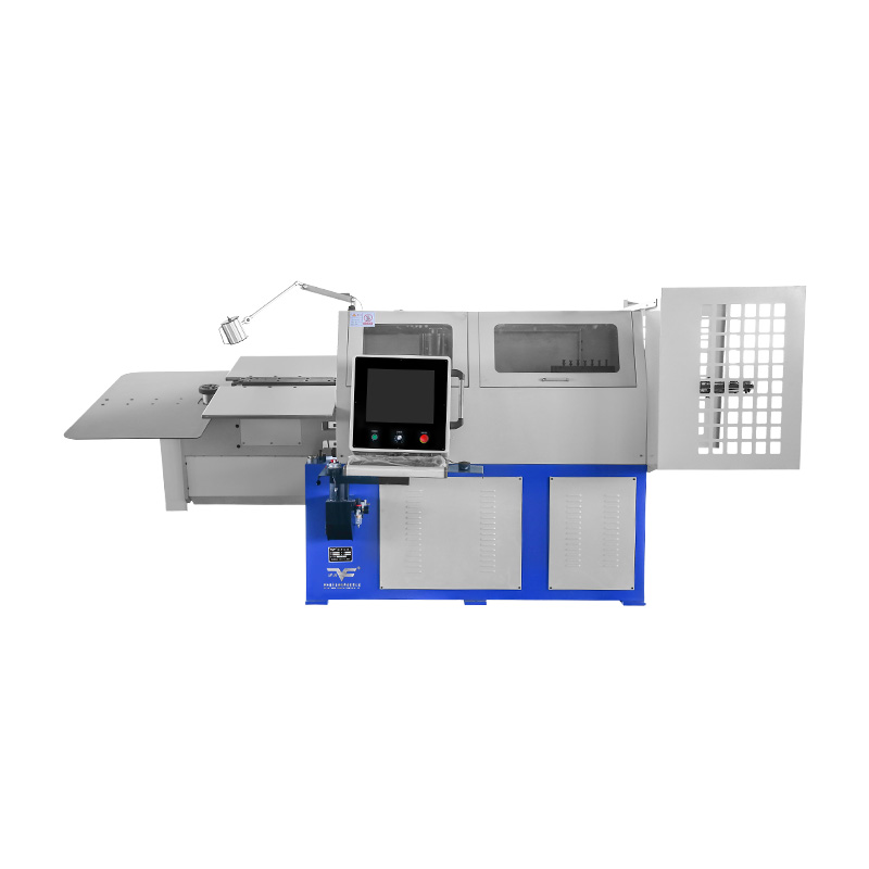
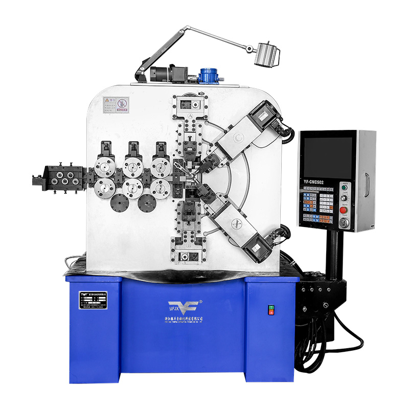
简体中文Camless Wire Bending Machine: Intuitive CAD Programming & 3D Simulation
Industry News-The capabilities of a machine are ultimately defined by the interface through which humans command it. In wire bending, the transition from a design concept to a finished physical part hinges on the efficiency and reliability of the programming process. Camless wire bending machine places a strong emphasis on their software systems, aiming to make this critical step more accessible, visual, and less prone to error—bridging the gap between engineering design and shop floor production.

From CAD Design to Machine Instructions: A Seamless Workflow
A central feature of camless wire bending technology is the tight integration of design and manufacturing data. Most software systems for these machines support the direct import of common computer-aided design (CAD) file formats, eliminating the need for manual recreation of part geometry. This means the precise wire path, bend angles, and segment lengths drawn by an engineer can be automatically translated into machine-readable bending commands. The software analyzes the CAD model to identify key features, calculates the good sequence of bending movements, and defines parameters like feed speed and bend force—all without requiring operators to manually input every detail.
This streamlined workflow drastically reduces the potential for human error that comes with manual data entry, ensuring the final part aligns closely with the original design intent. It also cuts down the time between design finalization and production startup, as there’s no lag from reinterpreting or reformatting design data. For teams handling frequent design changes or custom parts, this direct CAD-to-machine link becomes a major efficiency driver.
3D Simulation: Validating Processes Before Production
A transformative aspect of the software is its full three-dimensional simulation environment. Before any physical wire is fed into the machine, the entire forming cycle can be run virtually—a digital twin of the production process. This simulation shows the step-by-step movements of all machine components: the wire feeder advancing material, the bending heads rotating to create angles, and auxiliary tools guiding the wire into complex shapes. Operators can watch the part take shape on screen, zoom in on critical bends, and view the machine’s actions from any angle to spot potential issues.
This visual preview acts as a powerful safety net. It helps identify problems like tool collisions (where bending heads or fixtures might strike each other), incorrect bend sequences that would twist the wire, or insufficient clearance for multi-plane bends—all of which could advance to part defects, machine damage, or costly production stoppages in a real-world scenario. By resolving these issues in the virtual space, facilities avoid wasting material on test runs and ensure that the one physical part of the machine meets quality standards.
The Evolving Role of the Machine Operator
With CAD-driven programming automation and 3D simulation, the role of the machine operator shifts from manual coding to higher-level oversight. The need for deep, specialized knowledge of machine-specific programming languages is reduced; instead, operators can focus on tasks like managing production schedules, monitoring machine efficiency, and performing quality checks on finished parts. The learning curve for programming new parts becomes less steep, potentially allowing personnel with basic CAD proficiency to contribute to manufacturing preparation—streamlining workflow and reducing dependency on a small pool of highly specialized programmers.
Software as a Cornerstone of Camless Technology
The software behind camless wire bending is more than just an add-on—it’s a critical component that extends the machine’s functionality. By bridging design and production through seamless CAD integration and providing a virtual sandbox for process validation, it lowers barriers to operation and enhances procedural reliability. This focus on user experience and pre-production testing creates a more efficient, confident manufacturing environment where teams can tackle complex parts and frequent changeovers with greater ease.
Our Products //
Related Products
Copyright © Zhejiang Yinfeng Automation Technology Co., Ltd. All Rights Reserved. 
Sale Automatic Spring Making Machine